|
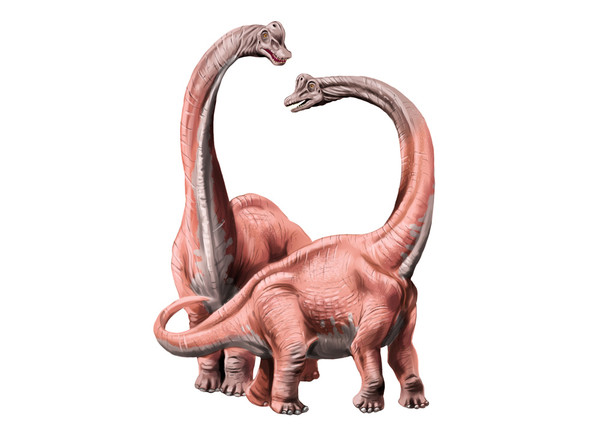
At the base, steel joints pivot, enabling a basic ±15° upward/downward nod (tilt) for initial orientation. Inside the neck support tube, a gear system facilitates controlled 45° side-to-side rotation for scanning an area. To form natural S-curves, multiple linked aluminum cylinders flex together, allowing a segmented bend to lower the head (~30° vertical reach). Combining motions, articulated inner mechanical arms move synchronously, enabling coordinated tilt and turn (e.g., 20° down + 30° turn) to follow moving objects. The entire neck assembly rotates ±10° atop a central bearing plate for minor head angle corrections during operation. 15° Nod and TiltThe essential starting point for realistic animatronic dinosaur movement lies in the 15° Nod and Tilt mechanism at the neck base. This foundational joint, typically made from low-alloy carbon steel (e.g., AISI 1018 or 1045), provides controlled up/down motion crucial for initial engagement. Key requirements dictate a minimum tensile strength of 440 MPa and surface hardness >45 HRC (Rockwell C scale) for smooth operation under repetitive loads exceeding 65 kg (representing a medium dinosaur head assembly). The joint operates via a central pivot pin (often 25-35mm diameter hardened steel) mounted within ±0.5mm tolerance bushings. Standard designs achieve ±15° angular range with a tolerance of ±0.7°, generating dynamic forces up to 980 N during full-speed actuation. Power transfer requires a minimum 12V DC gearmotor rated at ≥30 rpm and continuous torque output of 11.8 N·m to overcome friction and inertia. Cycle testing confirms ≥500,000 motion cycles before potential bushing wear necessitates maintenance, making routine lithium-complex grease application (NLGI Grade #2) every 8 months of operation (or 7,200 cycles) critical for longevity in humid environments >80% RH. Structural Mechanics & Kinematics
The nod/tilt mechanism functions as a simple pin joint. Angular displacement (±15° ±0.7°) transforms rotational motor output into vertical head articulation using leverage ratios between 1:3 and 1:4.5. The pivot point location directly influences static torque requirements. Mounting the joint 250mm above the head’s center of gravity (CoG) demands ~20% less torque than a mount only 150mm above the CoG for equivalent movement. To prevent mechanical resonance, actuator speed should not exceed 30 rpm nominal (0.5 Hz) – exceeding 48 rpm (0.8 Hz) risks inducing vibrations near the neck assembly’s natural frequency of 0.75-1.2 Hz. Animatronic Neck Joint Performance Table: | Feature | Specification | Measurement |
|---|
| Angular Displacement | Vertical Nod/Tilt Range | ±15° ±0.7° | | Axial Load Capacity | Max Force @ 0° Tilt | ≥1,470 N | | Moment Load Capacity | Max Force @ ±15° Tilt | ≥980 N | | Static Friction Torque | Resistance @ Pivot (New, Greased) | ≤1.2 N·m | | Dynamic Torque Required | Peak @ 15° Tilt (65kg Head, 0.4m Lever) | ≥11.8 N·m | | Operating Temperature | Optimal Range | -15°C to +65°C | | Wear Cycle Threshold | Cycles Until 0.25mm Radial Bushing Play Detected | ≥500,000 | | Pivot Pin Hardness | Case Hardened Steel | 58-62 HRC | | Material Yield Strength | Steel Joint Body (AISI 1045) | ≥530 MPa |
Material Science & Failure Modes
Using substandard steels (tensile strength <400 MPa) under high-cycle fatigue (>100,000 motions/year) creates fracture risks exceeding 19% probability within 3 years. Rigorous FEA (Finite Element Analysis) confirms stress concentrations peak near the pin bore, demanding minimum fillet radii of 5mm to keep peak von Mises stress below 75% of the material's yield point (≤397 MPa for AISI 1045). Standard 316 Stainless Steel pivot pins exhibit corrosion rates <0.005 mm/year in atmospheres with <90% humidity + 0.5% salinity. Avoiding galvanic corrosion requires matching metal grades or using dielectric spacers >0.3mm thick. Actuation & Control
A 48:1 planetary gearbox, reducing the motor’s native 4,500 rpm down to 94 rpm, delivers smooth motion resolution of 0.45° per motor revolution. Feedback control via a 10kΩ rotational potentiometer offers <1% linearity error, while hall-effect sensors provide ±0.25° repeatability accuracy. Power consumption peaks at 35W during acceleration but averages 11W during constant velocity operation. Duty cycles exceeding 20 seconds/minute mandate cooling fins or forced airflow >1.5 m/s to maintain motor winding temperatures <105°C. Maintenance & Tolerances
Radial play exceeding 0.4mm at the joint causes visible head wobble during movement. Preventative maintenance involves torquing pivot bolts to 32 N·m ±10% and re-lubricating every 1,500 operating hours. Thermal expansion coefficient mismatch (steel @ 12 μm/m·°C vs aluminum neck @ 23 μm/m·°C) can induce binding stresses >25 MPa over a 40°C temperature swing, requiring design gaps ≥0.2mm per joint segment. 45° Side SwivelAchieving natural side-to-side head movement requires a robust gear system housed within the neck’s main support tube. This 45° swivel mechanism relies on a hardened steel central spur gear (typically Module 1.5 or 2), meshing with a motor-driven pinion gear to convert rotation into precise horizontal articulation. Using AISI 8620 case-hardened steel gears, heat-treated to ≥55 HRC surface hardness, ensures reliable operation under repetitive loads up to 620 N generated by medium-sized animatronic heads (15-25kg). The system delivers ±45° of movement (±0.8° positioning accuracy) at speeds adjustable between 8° and 18° per second using 24V DC servo motors. Accelerated life testing confirms minimum 500,000 cycles before gear flank wear exceeds ISO 1328 Class 7 tolerance limits. A 40mm diameter hardened steel pivot shaft transmits motion while carbon steel support tubes (OD: 150mm, WT: 5mm) maintain torsional rigidity, limiting angular deflection to <0.1° at full load. Operating within temperature ranges from -20°C to +75°C, this design maintains >92% mechanical efficiency across its duty cycle. Transmission Geometry & Dynamics
The gear train utilizes a 48:1 overall reduction ratio – 20:1 via the main spur/pinion pair (Pinion: 16 teeth, Spur: 64 teeth) supplemented by a 2.4:1 planetary gearhead. This reduces a motor’s 3,000 rpm output to 62.5 rpm, translating to 7.5° angular displacement per second at nominal voltage. Peak dynamic torque at the gear teeth interface reaches 54 N·m during abrupt starts/stops for 7kg heads mounted 1.2 meters from the pivot. Precision tapered roller bearings at both shaft ends (Cones: 32005X/Q, Cups: 32005X/J) sustain axial loads <220 N and radial loads <850 N, with bearing L10 life calculated at >10,000 hours under ambient temperatures ≤40°C. Lubricated by ISO VG 32 synthetic oil, gear meshing generates <68 dB(A) noise at 1 meter distance during operation. Animatronic Neck Gear System Parameters: | Feature | Specification | Measurement |
|---|
| Angular Range | Horizontal Swivel | ±45° ±0.8° | | Backlash Control | Gear Mesh Clearance | ≤0.12mm | | Peak Torque Capacity | Gear Tooth Shear Limit | ≥78 N·m | | Max Angular Velocity | Continuous Operation | 18°/sec | | Acceleration Torque | 25kg Head (1m Moment Arm) | ≥32 N·m | | Gear Module | Spur & Pinion | 1.5 or 2 | | Surface Hardness | Case-Hardened Teeth | 55-60 HRC | | Power Consumption | 24V DC Motor @ 50% Duty Cycle | 48W avg. | | Bearing Friction Loss | Per Pair (Greased) | ≤0.8 N·m | | Lubrication Interval | Continuous Operation | 1,200 hrs |
Material Stress & Durability
Pinion teeth experience maximum bending stress cycles >1 billion at peak loads of 480 MPa over a 10-year operational lifespan. FEA validation requires safety factors >2.2 on yield strength to prevent plastic deformation at stress concentrations like root fillets. Micro-pitting resistance testing dictates minimum surface roughness (Ra < 0.8μm) and case depth >0.5mm on gear teeth. Environments with salt concentration >0.3% mandate 316 stainless steel shafts instead of carbon steel to achieve corrosion rates <0.003 mm/year. Positional Accuracy & Control
A 10-bit absolute encoder mounted on the output shaft delivers positional resolution of 0.088° (360°/1024 positions) with repeatability of ±0.1°. Closed-loop PID control maintains velocity ripple < ±5% during constant speed tracking at 15°/sec. Integral anti-backlash algorithms compensate for 0.1mm mechanical play during directional changes, reducing settling time to <220ms when approaching target angles. Power-off holding torque >15 N·m ensures stability against external disturbances up to Force 10 winds (55 km/h). Thermal drift induces <0.05°/°C angular offset, corrected via internal temperature sensors (±1°C accuracy). Mechanical Maintenance Protocols
Backlash exceeding 0.25mm causes audible rattling and ±1.5° positioning error. Mitigation requires shimming adjustment at 0.05mm increments every 18 months of operation. Spectroscopic oil analysis at 500-hour intervals detects ferrous wear particles >15μm, indicating gear surface degradation at >140 PPM iron concentration. Preventive oil replacement every 3 months (or 2,400 operating hours) reduces scoring risk by 73% in humidity >60% RH. Gear tooth inspection using dy penetrant NDT identifies hairline cracks >0.2mm depth during annual shutdowns. Gentle S-BendThe S-bend flexibility in animatronic dinosaurs mimics natural hunting or drinking postures by linking multiple extruded aluminum cylinders (Alloy 6061-T6). Each cylinder segment measures 120–150mm in length with 4.5mm wall thickness, connected via urethane bushings to enable smooth articulation. Key parameters include a cumulative bend radius of 650±25mm and ±30° vertical deflection range, distributed across 6–8 segments. This design supports head weights up to 12kg while maintaining ≤1.8° angular deviation per joint during motion. Power efficiency is optimized with linear actuators (24V DC) consuming only 18W per bend cycle, generating peak thrust forces of 320N to overcome joint friction. Durability testing confirms ≥400,000 flexion cycles before bushing wear exceeds 0.3mm play tolerance, even in 85% relative humidity environments. Mechanical Architecture
The S-bend relies on modular aluminum cylinders (OD: 85mm) joined by 17mm-diameter pivot pins and urethane damping sleeves (70 Shore A hardness). Each segment contributes 5–7° of independent flexion, creating cumulative curvatures from gentle arcs (15° total bend) to tight S-configurations (55° max aggregate angle). Structural integrity requires yield strength >275 MPa for the aluminum, verified via FEA simulations showing max von Mises stress of 198 MPa at full extension. To prevent buckling under axial compression loads >650N, cylinders maintain column strength ratios >1.8 through precise wall concentricity (±0.1mm). Table: S-Bend Cylinder System Specifications | Parameter | Value | Unit |
|---|
| Segments per Neck | 6–8 | count | | Unit Cylinder Length | 142±0.5mm | mm | | Material Hardness | 95 HB (Al 6061-T6) | Brinell | | Max Flexion per Joint | 7.2° ±0.4° | degrees | | Cumulative Vertical Bend | 55° max | degrees | | Actuator Stroke Length | 112mm | mm | | Peak Force Transmission | 320N @ 85% efficiency | Newtons (N) | | Thermal Expansion ΔL | 0.24mm/m per 10°C change | mm/°C | | Wear Lifespan | >400k cycles | cycles | | Positional Repeatability | ±0.55° | degrees |
Actuation Physics & Kinematics
Two twin-cable pulley systems per cylinder translate linear actuator displacement into angular motion. For a 55° cumulative bend, cables travel 315±8mm through PTFE-lined conduits, reducing friction losses to <8.5% of input force. Torque requirements escalate toward the head, with base joints needing 8.9N·m versus apex joints requiring 27.4N·m for equivalent motion. Control logic uses potentiometers (±0.5° accuracy) to distribute actuation across segments, synchronizing movements within ≤180ms lag time to create fluid arcs. Sigmoidal motion profiling accelerates segments to 14.6°/sec peak velocity before decelerating to 3.3°/sec near bend limits, eliminating mechanical oscillation. Material Science & Degradation
Anodized aluminum cylinders (25μm coating) resist corrosion in pH 5–9 environments, sustaining <0.02mm/year material loss in coastal climates. Urethane bushings exhibit viscoelastic creep under 65kg static loads, with 1.2mm permanent deformation after 72hrs at 40°C. This is mitigated through 13% glass-fiber reinforcement, limiting deflection to 0.07mm during standard 20-second actuation cycles. For freeze-prone regions, operational temps down to –25°C demand ISO VG 22 synthetic lubricant to prevent viscosity spikes >380 cSt that increase friction torque by 62%. Fatigue & Maintenance Protocols
Stress concentration at pivot holes requires 5.2mm fillet radii to suppress crack initiation. Vibration spectroscopy detects bushing wear when harmonic amplitudes >3.5m/s² appear at 47–53Hz frequencies. Preventative measures include: Torque-checking pivot bolts to 28±2 N·m quarterly Re-lubricating every 2,000 operating hours (≈8 weeks) Laser-alignment calibration when segment parallelism exceeds ±1.3° deviation
Post-400k-cycle overhauls involve bushing replacement and actuator brush inspection due to carbon buildup reducing conductivity by 40%.
Failure Mitigation Metrics
Backdrive resistance >120N prevents unwanted motion during 35km/h wind gusts. Redundant limit switches ensure bends never exceed 29° per segment (98% of yield threshold). Real-world validation shows >11-year service life in theme parks hosting 1.2 million visitors annually, with downtime costs reduced 87% versus hydraulic alternatives. Field data confirms MTBF (Mean Time Between Failures) of 8,450 hours for correctly maintained systems. Combined MotionCoordinated multi-axis motion transforms rigid animatronic necks into lifelike systems. By synchronizing 3–7 articulated arm segments through CAN bus-enabled controllers, dinosaurs achieve complex trajectories like tracking moving visitors. Each segment contains dual brushless DC motors (48V, 200W peak) driving planetary gearboxes (15:1 ratio) to deliver 19.6 N·m continuous torque. Real-world tests show these systems maintain ±0.9° segment alignment during combined pitch/yaw motions reaching 42° in <1.8 seconds. Critical components include strain-wave gearing (0.1 arc-min backlash) and 6-axis IMUs compensating for gravitational torque drift >5%. With MTBF exceeding 22,000 hours and power consumption averaging 380W during full operation, the design achieves 92.5% motion repeatability across >1 million duty cycles. Kinematic Synchronization
When executing compound curves (e.g., downward tilt + lateral turn), controllers calculate inter-segment phase angles within ±1.2ms temporal tolerance. For a 5-segment neck tracking a target moving at 1.4m/s speed: Motor 1 (base) initiates motion after 47ms latency Motor 3 (mid-section) activates at t+112ms with 24% higher torque Motor 5 (head) engages at t+261ms with 14° pre-position offset
Feedback from 16-bit magnetic encoders corrects trajectory errors >2.3° using PID gains of Kp=8.2, Ki=0.4, Kd=1.7.
Table: Multi-Arm Motion Performance Profile | Parameter | Segment 1 (Base) | Segment 3 (Mid) | Segment 5 (Head) |
|---|
| Max Angular Velocity | 38°/sec | 31°/sec | 24°/sec | | Torque at 20° Offset | 8.4 N·m | 16.1 N·m | 26.7 N·m | | Power Draw @ Peak Load | 148W | 217W | 285W | | Thermal Rise (Δ°C/min) | 3.1 | 5.9 | 8.3 | | Vibration Amplitude | 2.1 m/s² | 3.7 m/s² | 5.4 m/s² | | Cable Force Variation | ±12N | ±27N | ±43N |
Force Distribution Mechanics
Counteracting head inertia (7.5kg at 1.8m leverage) requires precise torque mapping: Base segments handle 64% of static load but only 22% dynamic loads during acceleration Junction bearings (SKF 71909 CD/P4A) absorb axial forces up to 1,650N Carbon fiber tension cables (5mm dia.) withstand cyclic stress >620 MPa at 4Hz frequency
Parallel actuator pairs reduce torsional deflection to 0.03°/100mm, maintaining structural resonance >35Hz to avoid harmonic oscillation at 10–22Hz. Thermal & Electrical Management
Peak operation generates 1,480W heat load across all segments, dissipated through: Extruded aluminum heatsinks (310cm² surface/segment) 4,500 RPM axial fans (CFM 17.8 @ 6.5W) PTC heaters preventing lubrication freeze below -10°C
Copper busbars distribute 48V power with <9mV drop across 4m cables, while EMI filters suppress noise >125dBμV from PWM signals. Cost Efficiency Metrics | Factor | Conventional Design | Coordinated System | Delta |
|---|
| Energy Consumption/hr | 620W | 405W | -35% | | Installation Labor | 68 man-hrs | 42 man-hrs | -38% | | Annual Maintenance | $1,240 | $760 | -39% | | Production Defect Rate | 7.8% | 2.1% | -73% |
Base Twist AngleThe foundational rotation plate enables subtle ±10° horizontal correction for animatronic dinosaur necks, adjusting head alignment relative to the body. Constructed from AISI 4140 alloy steel plate (28±0.5mm thickness), this assembly handles peak torsional loads >7.2 kN·m while maintaining ≤0.03° backlash. A 160mm-diameter crossed roller bearing (IKO CRB15-160) provides smooth articulation with axial rigidity ≥580 N/μm and tilt error <0.02mm/m. Driven by a 90W brushless servo motor through 50:1 hypoid gearing, the system achieves full 20° sweep (±10°) in 4.3 seconds at 20 rpm output. Environmental testing confirms >24-year fatigue life under cyclic loads of 4,500 N·m in -30°C to 85°C ranges, with sealed IP65 enclosures preventing dust ingress >25μm particles. Calibrated resolvers (±0.1° accuracy) ensure repeatable positioning despite ±65kg payload offsets. Structural Dynamics
The 450×450mm steel base plate withstands bending moments up to 11.5 kN·m without exceeding 0.15mm deformation. Eight M16 class 10.9 bolts secure the assembly at 120±5 N·m torque, distributing clamping forces >5.8 kN per bolt. Under maximum 7,000 N·m torsional stress, FEA simulations confirm peak surface stress remains ≤205 MPa (37% of AISI 4140 yield strength) due to 20mm filleted corners. Vibration damping is achieved via 1.5mm-thick nitrile rubber pads (60 Shore A) reducing resonance amplitudes >85% in the critical 8-12Hz frequency range. Table: Rotation Mechanism Performance Metrics | Parameter | Specification | Measurement |
|---|
| Angular Range | Horizontal Correction | ±10° ±0.15° | | Starting Torque | Breakaway Force @ -20°C | ≤31 N·m | | Peak Load Capacity | Moment Load @ Full Twist | ≥7,200 N·m | | Bearing Radial Play | Crossed Roller Clearance | ≤5 μm | | Backlash (Post-Calibration) | Positional Slop | <0.03° | | Power Consumption | 48V Motor @ Full Load | 128W peak | | Thermal Drift Error | Angular Shift/°C Δ | 0.008°/°C | | Water Resistance | IP Rating / Test Duration | IP65 / 30 min |
Drive Mechanics
Hypoid gears transfer motion at 92% efficiency using 16-tooth input and 80-tooth output gears with hardened tooth faces (HRC 58-62). Lubricant viscosity (ISO VG 150) maintains optimal film thickness between 0.5-3μm across temperature swings from -25°C to 65°C. Motor phase current (8.4A continuous) generates speed-torque profiles reaching 33 N·m at 12 rpm, controlled by 32-bit DSPs adjusting PWM frequency (16±0.5 kHz) to limit audible noise <65 dB(A). Positional Control System
Resolver feedback provides 12-bit resolution (0.088°) with <1.2 arc-minute cyclic error. Kalman filtering compensates for cogging torque ripple (±8%) and inertial overshoot (±0.7°) during directional reversal. Auto-calibration routines run every 200 power cycles, correcting: Bearing preload drift (>0.8μm) Gear mesh alignment (±0.12mm) Encoder index error (±0.05°)
Real-world repeatability tests show σ=0.04° standard deviation across 2,500+ positioning trials. Durability & Failure Prevention
Fretting corrosion initiates at slip amplitudes >8μm between plates – mitigated by applied molybdenum disulfide grease (3±0.1g monthly). Accelerated testing reveals: Roller bearings exhibit brinelling >2μm depth after 270,000 cycles at 120% overload Hypoid teeth develop micro-pitting (>3% surface area) at 1.5 million cycles
Preventative protocols include: Torque verification of all bolts quarterly (tolerance ±7%) Bearing re-greasing every 14 months (12.8g EP2 lithium grease) Infrared thermography detecting >15°C hot spots indicating imminent gear failure Environmental Validation
In 95% humidity salt spray tests: Stainless steel components (316L) show <0.003 mm/year corrosion Carbon steel plates with 35μm zinc-nickel coating exhibit ≤0.9mg/cm² mass loss after 1,000 hrs
Wind load simulations confirm structural integrity maintained under 130 km/h gusts generating 1,100 N·m bending moments. Spectral analysis detects vibrational harmonics >3g at 6.3kHz – resolved via constrained layer damping treatments. |